This document was formerly published as GEX document number 100-263. Contact GEX for a MS Word version of this document.
This is a procedure template from GEX Corporation and is not suitable for use unless edited and verified by the user. This template is designed to comply with the requirements of ISO/ASTM 51261 Practice for Calibration of Routine Dosimetry Systems for Use in Radiation Processing, but the user must incorporate all specifics for their use and assumes all responsibility for the use of this template.
1.0 PURPOSE
To establish a mathematical function that relates the change in dosimeter response to dose (Gy or kGy) traceable to a national standard with an associated level of uncertainty using irradiations performed in-plant with transfer-standard dosimeters from an accredited laboratory.
[This is a procedure template from GEX Corporation and is not suitable for use unless edited and verified by the user. This template is designed to comply with the requirements of ISO/ASTM 51261 Practice for Calibration of Routine Dosimetry Systems for Use in Radiation Processing, but the user must incorporate all specifics for their use and assumes all responsibility for the use of this template.]
2.0 SCOPE
Calibration of routine dosimeters for the qualification and routine monitoring of commercial and industrial radiation processes with electron beam, x-ray, or gamma sources.
Excluded from the scope is the calibration of thin film dosimeters for use in low energy electron beam applications (< 1.0 MeV). Instead, refer to Calibration of Dosimetry Systems Used in Low Energy Electron Irradiation.
3.0 DEFINITIONS
3.1 Dose Fractionation (‘fractionation’) – Delivery of dose in at least two separate irradiations comprising the total delivered dose.
3.2 Dosimeter Response – Reproducible, quantifiable effect produced in the dosimeter by ionizing radiation.
Discussion – In most cases, either the specific response or specific net response should be used depending on the dosimeter type. Generally, if the measured value before irradiation is stable or an insignificant value, then the user may consider using the specific response instead of the specific net response. Specific response is the measured value of the dosimeter signal post-irradiation per unit mass or thickness, depending on the dosimeter being used.
For example, below is a formula for the specific response that is often used for GEX B3 film dosimeters:
Specific Response = Ai / Tavg
Where:
Ai = Spectrophotometer absorbance value measured after irradiation
Tavg = Certified average thickness of the film batch or lot from the manufacturer
3.3 Dosimetry System Calibration – Irradiation of representative samples of routine dosimeters at an array of dose values, covering the range of intended use, to doses certified by an accredited laboratory, irradiated in a specified geometry or fixture.
Note: It is common practice to have a calibration specific to each device used to measure the dosimeter response or to develop a calibration that is applicable to all measuring devices (by combining their data).
3.4 In-plant (In-situ) Calibration Irradiations – Process of dosimetry system calibration where routine dosimeter samples and a transfer-standard dosimeter are simultaneously irradiated within the irradiator in a specified geometry ensuring the routine and reference dosimeters receive the same dose.
Note: Refer to the description of “Method 2” and subsequent sections on this subject in ISO/ASTM 51261:2015, Calibration of Routine Dosimetry Systems for Use in Radiation Processing.
3.5 Laboratory Calibration Irradiations – Process of dosimetry system calibration where routine dosimeter samples are irradiated in a radiation field at a laboratory with known rate of dose, optionally under controlled, fixed temperature conditions.
Note: Such irradiations generally require verification under conditions of use otherwise the chain of measurement traceability is broken. Refer to the description of “Method 1” and subsequent section on this subject in ISO/ASTM 51261:2015, Calibration of Routine Dosimetry Systems for Use in Radiation Processing.
4.0 GENERAL INFORMATION
The user calibrates the dosimetry system and not just the dosimeters which are only a part of the dosimetry system. The term “dosimeter batch calibration” is commonly used but is not completely accurate. The term “dosimetry system calibration” is the one embraced by ISO and ASTM and is defined herein. The title of this document is used to differentiate this process from that of calibrating the hardware (e.g., spectrophotometer) and references (e.g., optical filters) that comprise parts or hardware of the dosimetry system.
In-plant calibration irradiations allow the capture of influence quantities such as the environmental conditions (i.e.. temperature), dose rate(s), and dosimeter handling conditions that approximate actual usage. The alternative method of sending dosimeters for laboratory calibration irradiations is discouraged except where the user can justify it and verify the applicability to their own irradiation process.
Plan and conduct all irradiations such that they are reproducible for future calibration verifications and full calibrations. Document the irradiation conditions and record information related to special handling or special fixtures used in the calibration irradiations.
For a complete discussion of dosimetry system calibration principles and in-depth technical concepts consult Dosimetry System Calibration – Technical Information Report.
5.0 PREREQUISTES
5.1 Prerequisites for Dosimetry System Calibration
5.1.1 The dosimetry system IQ and OQ are complete.
5.1.2 The IQ of the radiation source and any conveyance system is complete, demonstrating a uniform area that is the size of the calibration phantom to be used.
5.1.3 Verification that the irradiator process settings to be used can achieve the lowest and highest targeted doses prior to performing the actual calibration irradiations using a generic calibration for the source being used.
5.1.4 Verification of the maximum temperature of high dose levels in accordance with any plan to keep temperatures below the recommended 60°C.
5.1.5 The user has defined the radiation pathway to be calibrated such that the dosimeters are irradiated using the pathway that they will be used to measure. For example, if the product makes multiple passes by the radiation source before completion, for the purpose of ensuring uniformity of dose to the product, the calibration should be conducted using that specific pathway.
5.1.5.1 Note: It is recommended that users calibrate the dosimetry system for each irradiation pathway unless they have sufficient evidence to demonstrate that the response function of the routine and transfer-standard dosimeters is not significantly affected by the difference in pathways.
6.0 PLANNING
6.1 Timeline and Timing of Dosimetry System Calibration
6.1.1 Budget 60 days for the completion of the dosimetry system calibration once the stock of dosimeters to be calibrated is available on site.
6.1.1.1 Two weeks for the procurement of the supplies purchased from external vendor(s) and assembly of internally available materials (Section 7.1).
6.1.1.2 One week for irradiation of the dose levels required for the calibration irradiations.
6.1.1.3 Two weeks for the analysis of the calibration, curve fitting, and calibration report creation/review/approval.
6.1.1.4 Three weeks of spare time to allow for any issues that arise.
6.2 Calibration Range, Temperature(s) and Dose Levels
6.2.1 The required range for the calibration is based on the application requirements for the dosimeter being calibrated.
6.2.1.1 The minimum dose to be calibrated is often based on the application needs for minimum specification dose and related min dose qualification testing requirements (e.g. ‘sterilization dose’).
6.2.1.2 The maximum dose expected during routine operations or other required ‘high dose’ testing with the irradiator typically defines the maximum dose to be calibrated.
6.2.1.3 The minimum and maximum dose requirements for the number of dose levels to be used to calibrate the required range for the [insert dosimeter name, e.g., ‘GEX B3’] dosimeter for use in the irradiation pathway [insert pathway identifier(s)] are shown in Annex A.
6.2.1.4 It may be advantageous to use multiple curve fits when there is broad range of dose required for various dosimetry activities. This can reduce overall uncertainty in areas of interest and allow lower order polynomial fits of the data sets to derive calibration curves. For example, a low range fit from 1 to 10 kGy for dose setting irradiations and a separate fit from 5 to 50 kGy for routine processing and dose mapping may provide lower average uncertainty versus a single curve from 1 to 50 kGy.
6.2.2 The temperature of irradiation at each calibration dose level is not and cannot be directly controlled. However, care is taken in the calibration design to realize temperatures that approximate those of routine use as best as possible. The following is considered:
6.2.2.1 Whenever possible, the maximum temperature during irradiation is kept below 60°C. Some techniques used to achieve this are:
6.2.2.1.1 Minimizing the maximum dose required for calibration. For maximum dose testing on products, fractionation of the total dose into 2 or more cycles may allow a significant reduction in the maximum dose to be calibrated.
6.2.2.1.2 Fractionation of the dose to the calibration dosimeters with some cooling in between the fractions.
6.2.2.2 The temperature profile during irradiation closely matches that of routine use.
6.2.2.2.1 When irradiating calibration dosimeters using the same irradiation pathway as routine processing, this is generally not an issue. However, when doses are fractionated, the effects of temperature are considered, and the irradiation protocol is designed to minimize differences in the temperature profile to the extent possible.
6.2.2.3 In general, with electron beam irradiation, any dose level should have an irradiation temperature that is greater than the preceding dose level.
6.2.2.3.1 When fractionating higher doses, the first fraction must be at least as high as the preceding dose. For example, if the preceding dose was 40 kGy, a dose of 60 kGy cannot be fractionated with 30 kGy + 30 kGy. It must be irradiated to at least 40 kGy on the first fraction with the remaining fraction comprising the difference (e.g. 45 kGy + 15 kGy).
7.0 PROTOCOL
7.1 Procure and Assemble the Materials
7.1.1 Calibration Phantom and Fixture
7.1.1.1 A phantom is used to secure the dosimeters in a geometry that ensures both the alanine transfer-standard dosimeter and the routine dosimeter (e.g. GEX B3) receive the ‘same’ dose. Consult with the dosimeter and/or calibration vendor for suggestions.
7.1.1.1.1 The design of the phantom should not be changed without the expectation in a change in the relationship of routine dosimeter to absorbed dose. Therefore, a specification for the phantom is listed in Annex B.
7.1.1.2 A fixture is used to ensure the consistent presentation of the phantom to the irradiation source.
7.1.1.2.1 For irradiation in large scale gamma irradiators using a tote or carrier system, the ‘fixture’ is the product tote or carrier in which the phantom is surrounded by homogeneous density material (simulated or actual product).
7.1.1.2.1.1 The phantom is located at a position in the load that is near the location where dosimeters typically receive the dose being targeted. For example, if the process is routinely monitored by using a reference position at the bottom center of the tote/carrier, do not place the phantom at the top of the load when possible.
7.1.1.2.2 Some ebeam irradiator designs and phantoms don’t require any fixture. For example, some material handling systems used with vertically oriented e-beams can pass the phantom through the e-beam without any additional fixture.
7.1.1.2.3 The calibration fixture ensures:
7.1.1.2.3.1 The distance from the phantom to the irradiation source is always fixed between calibration events.
7.1.1.2.3.2 The phantom is presented perpendicular to the radiation source. 7.1.1.2.3.3 The phantom does not experience unintended movement during the
irradiation that could cause variation in the geometry of the irradiations.
7.1.1.2.4 The design of the fixture is given in Annex C.
7.1.2 Transfer-Standard Alanine Dosimeters
7.1.2.1 The total number of transfer-standard alanine dosimeters that will be required depends upon the number of dose levels that will be irradiated. Refer to Annex A for the number required.
7.1.2.2 Request a quote from the vendor for transfer-standard alanine dosimeters such as GEX Part# S1000-X or equivalent.
[Note: Any laboratory accredited to ISO 17025 may be used if the certified dose measurements the lab issues will be traceable the United States National Institute of Standards and Technology (NIST) or the United Kingdom’s National Physical Laboratory (NPL). This procedure is written specifically for using GEX supplied alanines but references to specific GEX part numbers may be removed and replaced with information for other lab supplied alanines, if desired.]
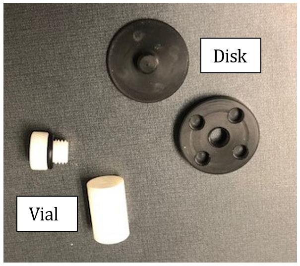
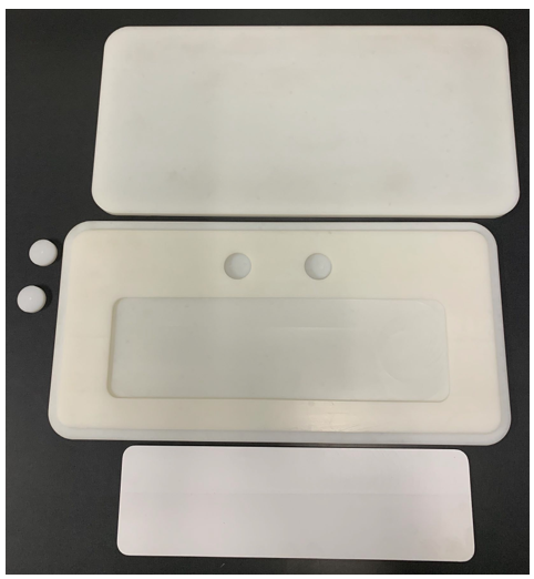
7.1.2.3 Specify a disk type holder or a vial type holder (refer to the pictures below) to contain the alanine pellets depending on the use-case (GEX and Risø Phantoms utilize the disk type). Consult with the laboratory if you are not certain.
7.1.2.4 The laboratory supplying the transfer-standard alanine dosimeters corrects the alanine dosimeter for the effect of temperature on the dosimeter response different from the reference calibration conditions by using established formulae. This process requires data from the user to define the irradiation temperature which requires knowledge of the starting temperature of the alanine and maximum temperature during irradiation.
7.1.2.5 Do not open the transfer dosimeter holders (disks or vials) under any circumstance unless instructed to do so by the vendor.
7.1.2.6 A set of controls accompanies every shipment of transfer-standard dosimeters. Always keep the controls with the rest of the dosimeters except for the irradiation.
7.1.2.7 Transfer dosimeters should be stored in air-conditioned office conditions upon receipt and until the execution begins. Temperature and RH deviations are acceptable but controlled conditions are the objective.
7.1.3 Equipment to Measure Starting Temperature of the Alanine Before Irradiation
7.1.3.1 The starting temperature should be as precisely determined as possible in degrees Celsius. Procure or verify availability of one of the following for measurement of starting temperature:
7.1.3.1.1 A calibrated infrared temperature gauge is preferred and used to directly measure the temperature of the phantom or alanine dosimeter (settings must be determined for measuring the material):
7.1.3.1.1.1 Vials are made of polystyrene plastic.
7.1.3.1.1.2 Disks are made of ABS plastic.
7.1.3.1.2 A calibrated thermometer (or equivalent) to be placed at the irradiation loading area to measure ambient temperature.
7.1.4 Estimating Maximum Temperature of the Alanine During Irradiation
7.1.4.1 In many applications, a measurement is required. However, in some electron beam applications, the temperature rise in the dosimeter can sometimes be estimated by the laboratory. Consult with the laboratory vendor when temperature measurement is difficult or impossible and a method for best estimation is agreed in advance of the irradiations.
7.1.4.2 Any device used to measure temperature during irradiation must survive the irradiation process with an accurate measurement.
7.1.4.3 Procure or verify availability of one of the following:
7.1.4.3.1 Irreversible temperature labels such as GEX Part# P8003 or equivalent. One label is required for each transfer-standard alanine dosimeter to be used (refer to section 6.2).
7.1.4.3.2 For irradiations in electron beam only, a calorimeter may be used.
7.1.4.3.3 Other (not described herein).
7.1.5 Samples of Dosimeter Stock to be calibrated
7.1.5.1 A representative sampling of the dosimeters was retained at the time of receiving inspection for the dosimeter stock to be calibrated. See Dosimeter Stock Receiving Inspection, for more information.
7.1.5.1.1 From the set of stock samples, retain [user specify the number – e.g., ‘6’] individual dosimeters to be used for each dose level to be irradiated.
7.1.5.1.2 If an appropriate sampling was not taken during receiving inspection or is unavailable, follow the sampling principles specified in Dosimeter Stock Receiving Inspection, to generate the required samples for the calibration irradiations plus some extra quantity in case of need.
7.1.5.2 If the stock is going to be calibrated for the first time, use samples retained during receiving inspection for the purpose of calibration or sample the entire stock representatively to obtain enough samples to conduct the calibration.
7.1.5.3 If the stock of GEX B3 dosimeters is being recalibrated and only a portion of the original inventory remains, use samples that were retained at the time of receiving inspection provided they have been stored in the same environmental conditions as the stock of unused dosimeters that remain in-stock and that there are enough samples to complete the recalibration. Otherwise, the remaining balance of the stock should be resampled. The original samples should be retained but not used in the calibration irradiations.
7.1.6 Calibration Data Workbook
7.1.6.1 [If using GEX Calibration Services, a ‘Calibration Data Workbook’ is provided to record all information for both the transfer-standard alanine dosimeters and the routine dosimeters. Note the GEX document number QF-77-01, Calibration Data Workbook or QF-77-03 Calibration Audit Workbook.]
7.1.6.2 Obtain the Workbook (or make your own) prior to the need to complete irradiations.
7.1.6.3 All information is formally recorded in this Workbook although there will be other primary records such as the process report(s) from the irradiator and the measurement reports from the dosimetry system.
7.1.6.4 Data will be transcribed or copy/pasted into the Calibration Data Workbook. Therefore, all data must be reviewed fully before any data analysis and processing in future steps.
7.2 Transfer-Standard Alanine Dosimeters
7.2.1 The transfer standard dosimeters are accompanied by information and a worksheet for completing irradiation information for each transfer dosimeter by its serial number. Make copies of the enclosed paperwork or obtain an electronic copy from the vendor.
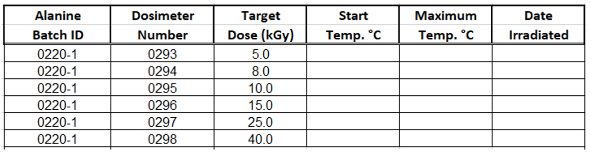
7.2.1.1 On the electronic or paper form from the laboratory, assign target doses to the alanine transfer-standard dosimeters.
Note: Generally, the lab will measure the alanine dosimeters from lowest dose to highest dose, so it is helpful to allocate them in sequence from low to high dose, but not mandatory.
7.3 Dosimeter Original (unirradiated) Absorbance
7.3.1 Verification of the unirradiated absorbance (‘Original Absorbance’ – ‘Ao’) at the time of calibration is a common practice with optically measured dosimeters and is required when using the specific net absorbance to determine the dosimeter response.
7.3.2 The receiving inspection of the new stock included a verification of the original absorbance, see Dosimeter Stock Receiving Inspection.
7.3.2.1 If the stock is greater than 2 months since initial inspection, retest the original absorbance using representative samples from the stock using a similar procedure and determine the average on each spectrophotometer at the time of calibration.
7.4 Labeling and Separation of the Dosimeters
7.4.1 The routine dosimeters are labeled to identify the dosimeters within each dose level. There is no specific requirement for labeling. One option is to label with the target dose and sample number (different than the ‘dosimeter ID’) using the format XX-YY, where XX is the dose and YY is the sample number as shown in the picture below.
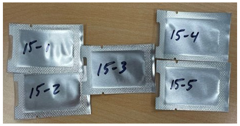
7.4.2 Label the set of pouches for each dose level as noted in the step above using felt-tip pen.
7.4.3 Place the dosimeters for each target dose level into a small poly zip-bag with the alanine(s) with which they will be irradiated, ensuring that the correctly labeled routine dosimeter pouches for each dose level are placed with the alanine ID number(s) assigned to receive the same target dose.
7.5 Preparation for Calibration Irradiations
7.5.1 Take all materials and setup a temporary workstation in the product loading area. The materials must equilibrate to the ambient conditions at the location where the loading of the irradiator occurs to simulate the routine temperature conditions.
7.5.2 Prepare one phantom at a time with the materials based on the total number of phantoms available.
7.5.2.1 Place dosimeters in the appropriate calibration phantom.
7.5.2.2 [If using a commercially procured phantom, refer to the manufacturer’s product document for complete instructions for preparing the phantom (see References section) and paste that information into this document along with any additional pictures that may be required. Otherwise, specify the procedure with pictures here].
7.5.2.3 Do not overload the phantom sample compartment with dosimeters or other materials that may produce shadowing or shielding of dosimeters. Instead, use a second phantom irradiated to the same dose, which may or may not require an additional alanine dosimeter.
7.5.2.4 For organization, label the outside of each phantom with a tag, piece of tape, etc., noting the target dose for the irradiation and any specifics for phantom orientation that are required.
7.5.3 Process the phantom to the target doses according to the facility’s standard procedures. The calibration dosimeters and the transfer dosimeter should be placed perpendicular to the electron beam or parallel to the gamma source rack to achieve dose uniformity.
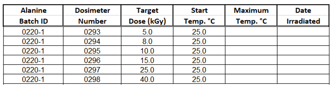
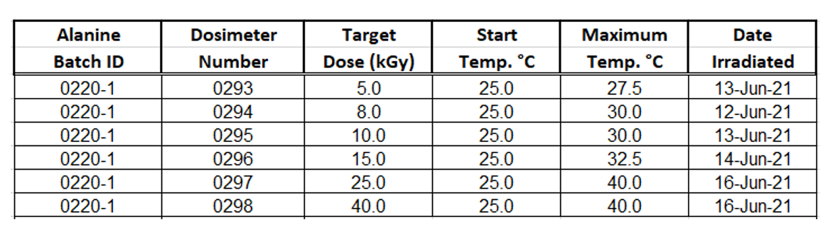
7.5.4 Measure and record the starting temperature for each dose level on the laboratory worksheet.
7.5.5 Place the phantom on the calibration fixture and prepare any additional materials, carriers, totes, etc. for irradiation.
7.5.6 Set the process parameters for the dose being targeted and execute the irradiation of the phantom.
7.5.7 When the irradiation is complete and the phantom can be retrieved, review the setup for any change from the geometry prior to irradiation and document any findings, if any.
7.5.8 Remove the phantom and place on a level surface. Remove the transfer standard alanine and the routine dosimeters from the phantom without delay. Delaying could artificially incubate the dosimeters in the phantom and may not simulate routine handling conditions.
7.5.9 Document the maximum temperature during irradiation and the date of irradiation on the laboratory form.
7.5.10 Retain processing records for each dose level irradiated.
7.5.11 Allow the phantom and all the materials to cool to room temperature in a well-ventilated area.
7.5.12 A phantom may not be used again until it can be sufficiently cooled to the approximate ambient room temperature. Phantoms may be laid on a concrete floor to help with heat dissipation.
7.5.13 Once the dosimeters are cool, place the dosimeters back into their poly-zip bag along with any irreversible temperature label used during the irradiation of those dosimeters.
7.5.14 Return the dosimeters to the dosimetry laboratory for processing.
7.6 Post-irradiation Handling of the Transfer-Standard Alanine Dosimeters
7.6.1 Place all of the laboratory’s alanine dosimeters, including any spare or control dosimeters, back into any bags or envelope in which they were provided by the lab. Include a copy of the completed laboratory worksheet with the irradiation dates and temperature information that the lab requires. Retain a copy for internal records as well.
7.6.2 It may be beneficial to wait until all routine dosimeters are measured on at least one spectrophotometer to determine if there were any target doses that appear to have been processed incorrectly. Some laboratories typically provide a spare transfer-standard dosimeter in case there were any issues found during irradiation of a target dose point. If issues are encountered, repeat the target dose point with the spare alanine, new sample dosimeters, and a new temperature label (if used). Note any issues and repetitions on the laboratory worksheet.
7.6.3 Follow the written instructions for returning the transfer-standard alanine dosimeters to the laboratory. Use express courier service.
7.6.3.1 There is no need to mark the package “do not x-ray”. Such doses are below the threshold of concern for impacting the accuracy of the laboratory’s measurements. The laboratory control dosimeters will be verified by the lab and any unintended dose in transit will be measured and accounted for, if any.
7.6.3.2 Do not include ice or any other liquid in the package back to the laboratory. Alanines are susceptible to liquid, and damage can occur if they get wet.
7.7 Post-irradiation Handling of the Routine Dosimeters
7.7.1 Heat-treat the dosimeters using standard procedures and equipment at [1 to 1.5 hours] after irradiation.
[It is recommended to specify the exact time interval for heat treatment of the calibration dosimeters. The user may validate the use of a wider interval for routine dosimetry and account for any additional variance such allowance may cause as a component of measurement uncertainty. However, the attempt to capture variance in heat treatment time after irradiation is not recommended as part of the dosimetry system calibration.]
7.7.2 Heat-treat all dosimeters within this time interval prior to beginning any measurements.
7.8 Routine Dosimeter Measurement with Data Review and Analysis
7.8.1 Prior to measurement of the dosimeters, complete a [short or full] performance verification on each spectrophotometer.
7.8.2 Measure all dosimeters in a single measurement session on each spectrophotometer following routine procedure.
7.8.2.1 When using DoseControl, a calibration is required to measure dosimeters. Either use an existing calibration with automatic barcode scanning disabled or use a temporary curve for the batch being measured for calibration.
7.8.3 Record all required information about the instrument, dosimeter batch, etc., as required by the worksheet.
7.8.4 Repeat this for each instrument.
7.8.5 Retain all dosimeters under controlled conditions until the calibration curve fitting and reporting is complete and accepted for use. Dosimeters may need to be re-measured or investigated for anomalies after data analysis.
7.8.6 Record any informational comments, deviations, or abnormalities that GEX technical personnel should be advised of before preparing the calibration curves.
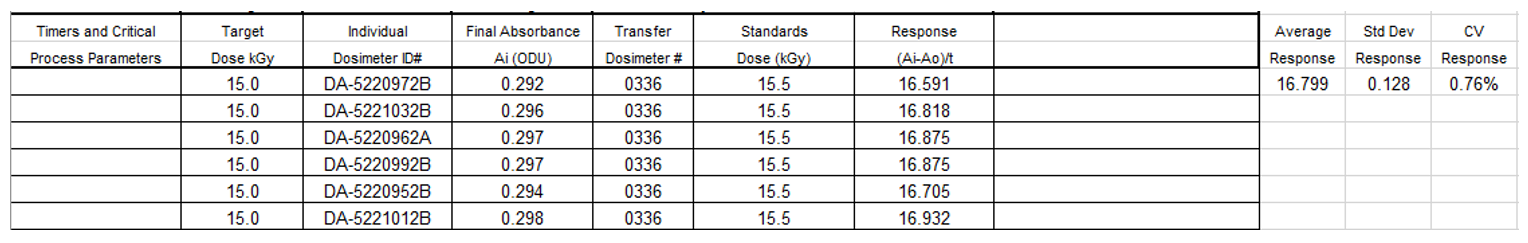
7.8.7 After filling in the Calibration Data Workbook, review it for accuracy (data entered is correct – i.e. the spectrophotometer ID, for example), completeness (all fields are completed), and typographical errors.
7.8.8 Review the C.V.% of dosimeter response at each dose level on each instrument. If the value exceeds 2%, verify the data for any errors in entry and evaluate the need to remeasure any large deviations (for example, if one measurement varies by 300%, it should be remeasured prior to the curve fitting process).
7.9 Calibration Curve Fitting
[This section is written for companies using GEX’s services. Replace the text in this section if performing your own fitting or using another service.]
7.9.1 Send a copy of the completed Calibration Data Workbook and any other relevant process data to GEX via email to labcalserv@gexcorp.com.
7.9.2 The data will be reviewed for completeness and analyzed prior to the performance of the curve fitting process.
7.9.3 The efficacy of the data is extremely important to the accuracy of the calibration curve. In addition to the user’s routine controls to ensure the efficacy of measurement, the data must be assessed and unexpected variability in the data must be reviewed for effect.
7.9.3.1 Remeasurement of dosimeters may be requested, and the user should conduct remeasurement in accordance with routine procedure.
7.9.3.2 Cases of potential outlier data are assessed and evaluated in accordance with ASTM E178, Practice for Dealing with Outlier Observations.
7.9.4 The calibration curve fitting will be performed according to the specifications provided to GEX.
7.10 Uncertainty
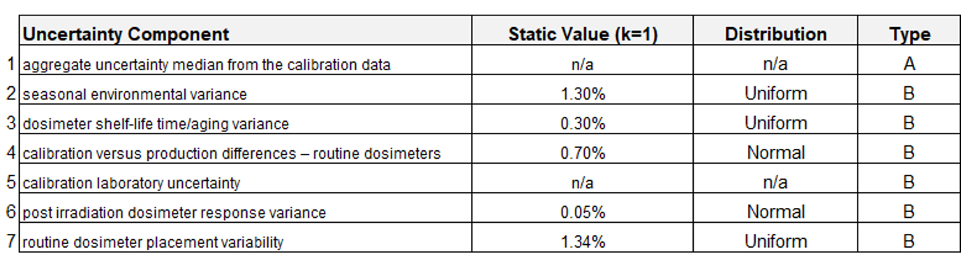
7.10.1 The measurement uncertainty is determined by adding Type A and Type B uncertainty components in quadrature, expanded to a level of confidence at k=2.
7.10.1.1 The Type A component is an aggregate value determined from each calibration data set.
7.10.1.2 The Type B components are static values determined separately from the calibration and used repeatedly with each calibration.
7.10.2 The components of uncertainty have been evaluated and are established in the table below. Values marked ‘n/a’ vary with each calibration. All other values are fixed.
7.10.3 The value of each component is determined and rationalized separately. Refer to Developing and Using Uncertainty Statements, for more information.
[Replace with an internal company document reference or insert a new Annex to include within this document, as applicable]
7.10.4 GEX will prepare the expanded overall uncertainty for each calibration curve using the customer specified type B uncertainties combined in quadrature with the “median type A” calibration uncertainty determined from the Dose Estimate Table of each calibration curve. If not specified, GEX will use default Type B values.
7.11 Calibration Report
7.11.1 The raw Calibration Data Workbook complete with curve fitting is received from the vendor. It is reviewed for data accuracy and content against the original measurement reports and records, and each curve fit is reviewed.
7.11.1.1 Goodness of fit is evaluated statistically and visually and is explained in detail by the Calibration Laboratory. [Such as the GEX Calibration Certificate provided with the S1101/S1102 Calibration Service and Audit Service.]
7.11.1.2 Ensure the overall range of the calibration curve(s) meet the requirements stated herein.
7.11.1.3 Review the uncertainty of each curve fit to ensure that all requirements herein are met.
7.11.2 Upon successful completion of review, request the vendor to complete the report. Otherwise, discuss with the vendor, execute any changes or additions to the calibration or report, and resolve until the report can be accepted.
7.11.2.1 If the calibration is unacceptable, make any changes to internal process and vendor and repeat the dosimetry system calibration as soon as possible.
7.11.3 The vendor will complete the report and send at minimum an electronic copy of the entire report. Report contents:
-
Summary
-
Requirements
-
Laboratory worksheet and dose certificate
-
Measurement worksheets
-
Measurement data statistics
-
Curve fit(s) and fit statistics
-
Dose look-up table(s)
7.11.4 In addition to verification of the data accuracy and completeness of the calibration records, the calibration review includes verification that the specified calibration target doses and maximum temperatures are within specified limits before the calibration can be approved and authorized for use at the facility.
7.11.5 Formally approve the calibration report with a signature and date.
7.12 Implementing the Dosimetry System Calibration
7.12.1 Import or otherwise enter coefficients and information into DoseControl’s Calibration configuration screen. Refer to DoseControl Software User Guide, for more information.
7.12.2 Verify the output of the software against the dose table provided for the curve being configured.
7.12.3 Prior to actual implementation, it is appropriate to perform side-by-side comparisons on actual production irradiations as a final verification. This will also determine whether process setting adjustments will be required in order to successfully achieve dose targets with the new dosimetry system calibration(s). Adjustments should typically be within the expanded uncertainty of the Transfer-Standard Dosimeter measurement uncertainty at k=2 (e.g. “3.0 %”).
8.0 REFERENCES
-
ASTM E178 – Practice for Dealing with Outlying Observations
-
ISO/ASTM 51261, Practice for Calibration of Routine Dosimetry Systems for Radiation Processing
-
NPL CIRM 29, Guidelines for the Calibration of Routine Dosimetry Systems for use in Radiation Processing
-
ANSI/AAMI/ISO 11137, Sterilization of health care products – Radiation
ANNEX A: Calculation of Dose Levels Comprising the Dosimeter Calibration
Dosimeter Type: [insert dosimeter name, e.g., ‘GEX B3’]
Irradiator Pathway Name(s): [insert identifier]
|
Minimum Required Dose (kGy): |
2.0 |
|
Maximum Required Dose (kGy): |
30.0 |
|
|
|
|
Target #: |
Calculated Dose (kGy) |
|
1 |
1.9 |
|
2 |
3.3 |
|
3 |
5.8 |
|
4 |
10.0 |
|
5 |
17.4 |
|
6 |
30.3 |
ANNEX B: Dosimeter Calibration Phantom
|
Irradiator Pathway Name(s): |
[insert identifier, e.g., ’10 MeV Horizontal Ebeam’] |
|
Phantom Type: |
[insert identifier, e.g., ‘GEX 10 MeV Ebeam Phantom] |
|
Material: |
[insert information, e.g., ‘High impact polystyrene (HIPS)’] |
|
Bulk Density: |
[insert identifier, e.g., ‘1.0 g/cm3] |
ANNEX C: Dosimeter Calibration Fixture
|
Irradiator Pathway Name(s): |
[insert identifier, e.g., ’10 MeV Horizontal Ebeam’] |
|
Phantom Type: |
[insert identifier, e.g., ‘GEX 10 MeV Ebeam Phantom] |
|
Material: |
[insert information, e.g., ‘2.25” Polyethylene foam’] |
|
Bulk Density: |
[insert identifier, e.g., ‘0.1 g/cm3] |
[User insert picture of fixture, if applicable]
Disclaimer -The information contained in this document is provided “as is” and is not a substitute for the user’s professional judgement. It is provided as a convenience to those using products provided by GEX Corporation who have sufficient technical skills to evaluate and properly apply the information in this document. It is the responsibility of the user of this document to ensure that the information in this document, and the use of such information, is accurate, complete, applicable to the product, suitable for the user’s purposes, and in compliance with all laws and regulations. GEX Corporation believes the information provided in this document is accurate and reliable as of the time of writing, but it undertakes no obligation to update or correct this document. GEX Corporation may, but is not required to, make changes to this document at any time without notice. By using the information in this document, the user represents and warrants that he or she has the skills necessary to properly understand and apply this information and that he or she will comply with all applicable laws and regulations including, without limitation, those relating to medical devices, pharmaceutical products, or other applicable industries. The user assumes all risks associated with using this information and any results or output resulting from the application of this information to GEX Corporation’s products. The user agrees not to hold GEX Corporation liable for any errors or omissions contained within.