
The document was formerly published as GEX document number 100-203.
Overview
The practice of dosimetry involves estimating absorbed dose from a quantifiable change in a “dosimeter”. A “dosimeter” is made from a material that has a unique measurable property that responds in a predictable way when exposed to a source of ionizing radiation. Calibration is the process of relating a dose traceable to a national standard to the change in the measurable property of a dosimeter.
It is important to be aware that one does not calibrate dosimeters but rather one calibrates a dosimetry system for use with a specific batch of dosimeters. The calibration activity results in establishing a response function for a specific batch of dosimeters and instrumentation that is appropriate for application in a specific radiation process under conditions equivalent to those used in the calibration.
A dosimetry system is comprised of the measurement instrumentation, its references and procedures, record forms and any software used to control operational performance of the dosimetry system. The dosimetry system also includes a representative stock of a dosimeter batch along with the specific dosimeter batch calibration response function (curve coefficients).
The ability to successfully repeat or reproduce the calibration process involves development of a calibration practice (formal procedure) used to control the calibration process. The calibration procedure should undergo verification testing to demonstrate that its use can effectively and reproducibly achieve temperature and dose targets that are similar to those encountered during routine processing.
Simple mistakes in planning or errors in execution of a calibration can lead to significant error or bias in final dose measurement outcomes. The intent of this document is to provide information relevant to considerations along with recommendations for development and implementation of a successful dosimetry system batch calibration practice.
Dosimetry System Calibration Requirements
Calibration of the dosimetry system must be carried out to establish a unique response function for each specific batch of dosimeters used with the dosimetry system. GEX conducts its value-added dosimetry system calibration services in accordance with guidance provided in current revisions of the following published industry documents:
ISO/ASTM 51261 Guide for Selection and Calibration of Dosimetry Systems for Radiation Processing
NPL CIRM Report 29 Guidelines for the Calibration of Dosimeters for Use in Radiation Processing
All GEX dosimetry system calibration services are controlled using internal formal work instructions and procedures designed and maintained to satisfy industry guidance. The GEX published dosimetry system batch calibration practice document Performing a Dosimeter Batch Calibration, provides a generic dosimetry system batch calibration procedure that can be readily adapted to specific user requirements. Contact GEX to discuss your specific calibration requirements and source your calibration needs.
Calibration Prerequisites
Dosimetry system calibration assumes the following prerequisites have been completed:
-
dosimetry system characterization was completed (see Appendix B);
-
standard operating procedures appropriate to control and optimize dosimetry system performance have been developed;
-
dosimetry system verification and validation testing has been completed (includes instrumentation and related software);
-
appropriate personnel have been trained in related procedures;
-
dosimetry system instrumentation and equipment calibrations are current.
Dosimetry System Calibration Considerations
Some dosimetry users are required by specific application guidance documents to establish a calibration response function for each batch of dosimeters that is traceable to a national standard through an unbroken chain of dose comparisons with associated levels of uncertainty. Further, these calibrations are also required for each irradiator and each irradiator process pathway (different conditions such as dose rate, energy, temperature, etc.) in addition to calibrations for use with each individual dosimetry system or set of instrumentation using that specific batch of dosimeters.
Other dosimetry users that do not operate under specified guidance requirements may find it acceptable to simply use a generic dosimeter batch calibration response function (sometimes provided by the dosimeter manufacturer/supplier). A rationale for this can be: dosimetry is only used to control the relative uniformity of the process and specific dose outcomes do not require site-specific traceable dose accuracy. In this situation, the response function need only be highly reproducible and related to a consistent internal or external reference.
This latter point is commonly found in industrial processes where the user relies upon final product properties or performance measurements and does not use dose measurement outcomes for production quality control practices.
Therefore, this latter group of dosimetry users does not have a need to establish their own calibration practice and can simply accept and implement a dosimeter batch representative “generic” calibration from an acceptable source. This user group accepts generic calibrations for use in their facility by demonstrating dosimetry effectiveness as it relates to their process application outcome.
Methods of Calibration
The two calibration guidance references identified above both describe the same two methods of calibration that may be used to calibrate dosimetry systems traceable to a national dose standard. The two methods are commonly referred to as “laboratory” calibration and “in-situ” calibration.
A “laboratory calibration” is carried out by irradiating representative samples of a batch of dosimeters under specified and monitored constant temperature and dose rate conditions in a research gamma irradiator to achieve the desired targeted doses. Without in-situ verification by the user (discussed below), this method can be considered to render a “generic” calibration for a dosimetry system.
This calibration method is generally used to calibrate reference and transfer standard dosimetry systems but may also be used to calibrate routine dosimetry systems where conditions of routine use are approximately equivalent to those of the calibration irradiation conditions, provided post-irradiation stability of the dosimeter response can be assured or controlled.
Alternatively, an “in-situ” (also referred to as: “in-process” or “in-plant”) calibration is carried out by irradiating representative samples of the routine batch of dosimeters alongside calibration laboratory supplied reference transfer standard dosimeters in the user’s irradiation plant under normal irradiation process conditions controlled to achieve the required range of calibration target doses.
This method is used to calibrate routine dosimetry systems under conditions that approximate normal processing, to verify an existing calibration for continued use, or to provide evidence to validate a generic calibration response function for use in a specific irradiator.
It is suggested in ISO/ASTM 51261 and NPL CIRM Report 29 that a laboratory calibration may be validated for use in a specific radiation process facility by successfully passing a calibration “verification audit” of the calibration. However, at this time, no guidance is provided as to the acceptance criteria although the NPL CIRM Report 29 does indicate the potential of applying a linear correction factor to the calibration function.
Unfortunately, all dosimetry systems are known to be influenced by temperature and the ability to correct a laboratory calibration for use in an irradiation process where temperatures increase with dose is complex and may lead to the introduction of bias in the calibration resulting in an over or under estimation of dose, or both.
Note:
GEX takes the position of recommending that any dosimetry system used as a routine dosimetry system with a national standard traceable dose requirement, be calibrated using the “in-situ” method because this method, when properly designed, can better account for the influence of radiation process temperatures and dose rates by capturing
their affect in the calibration itself rather than attempting to estimate their impact on the calibration result. An exception to this rule is the use of low dose range fixed dose rate and temperature calibration for an application such as food irradiation where temperature change associated with doses up to a few thousand Gy would not be expected to have significant effect on dosimeter response.
On the other hand, any dosimetry system used as a reference or transfer standard dosimetry system must be calibrated under fixed temperature and dose rate conditions so that calibration adjustment factors can be properly established, accounted for, and applied when these systems are used to calibrate other dosimeter systems or to measure transfer doses under the various conditions found in different irradiation process facilities.
Calibration Uncertainty
Uncertainty is a statement of the level of accuracy associated with the doses estimated from a given calibration. Detailed discussion can be found in the ISO/ASTM 51707 Uncertainty Standard. The 51707 standard builds on the ISO Guide to Uncertainty in Measurements (“GUM”) document that is used by countries to facilitate international trade by providing a means of mutual recognition of each country’s measurement standards. See also the GEX Technical Report Developing and Using Uncertainty Statements.
Dose traceability to a national standard is established through an unbroken chain of calibration comparisons with their associated uncertainties. Therefore, calibration uncertainty, or the level of dose accuracy, expands with each link in the chain of calibrations coming down from the national standard.
The user is responsible for determining those components of uncertainty associated with their calibration and routine use of their dosimetry system to be added to the uncertainty associated with the calibration doses stated by the calibration laboratory. This combined overall standard uncertainty is typically expanded using a coverage factor of k=2 to arrive at an approximate 95% confidence interval.
Dosimetry System Calibration Maintenance
A dosimetry system calibration is generally accepted as usable for approximately one year assuming instrumentation performance can be demonstrated as maintainable within calibrated limits and the batch stock of dosimeters maintain their response to dose over the calibration period within expected limits.
Periodic in-situ verification audits are used to provide evidence that an existing calibration response function provides dose estimates in agreement with national standard traceable doses within acceptable accuracy limits or established calibration uncertainty limits. The frequency of calibration audits is user defined.
Note: GEX recommends using periodic in-situ calibration audits coupled with a daily instrumentation checks program to effectively maintain dosimetry system calibrations. Acceptance criteria for calibration audits should utilize a statistically based approach. GEX recommends use of the calculated original calibration uncertainties combined with appropriate seasonal components. Acceptance within k=2 and rejection outside k=3 with investigation or repeat required for results between these limits are the recommended criteria.
APPENDIX A: PLANNING AND EXECUTING DOSIMETRY SYSTEM CALIBRATION
All measurement equipment and instrumentation must be calibrated prior to its use in dosimetry system batch calibration activities. The calibration of dosimeter signal measurement equipment (e.g. spectrophotometers) should be verified just prior to making measurements of dosimeters irradiated for calibration.
GEX Calibration Services will help you with most of the planning phases described below, if you utilize our service. However, familiarization with the process by the end-user is the best recipe for a successful calibration.
For specific recommendations on executing a calibration, please see our recommended procedure, Performing a Dosimeter Batch Calibration,
Calibration Design Plan
Regardless of the calibration method selected, the user will need to select the calibration laboratory or laboratories that will provide the source of traceable calibration dose including selection of the transfer dosimetry system to be used in the in-situ calibration or calibration verification audit irradiations.
The selection of an appropriate transfer dosimetry system may limit the calibration laboratory choices due to availability of certain dosimeters and dose range limitations. It should also be noted that the transfer dosimetry system selected should be of a different type than the dosimetry system being calibrated to minimize the potential of introducing bias into the calibration.
Calibration Laboratory Selection
Five calibration laboratories are generally recognized and used by industry around the world that can provide certified dose traceable to a national standard for high dose applications. GEX routinely works with these laboratories in the performance of traceable calibration services for customers.
-
GEX Corporation - GEX is accredited by NVLAP to ISO/IEC 17025:2017 certified High Dose Reference Laboratory. NVLAP Calibration Lab Code 600080-0.
-
NIST - National Standards Laboratory of the United States of America
-
Risø HDRL - DANAK ISO 17025 certified High Dose Reference Laboratory
-
NPL - National Standards Laboratory of the United Kingdom
-
MDS Nordion - NVLAP ISO 17025 certified High Dose Reference Laboratory
Note: GEX advises that none of the above calibration laboratories have gamma calibration fixtures that can adequately accommodate GEX B3 “DoseStix” Dosimeter product packages. Contact GEX for special calibration planning in the event your needs require a fixed temperature and fixed dose rate laboratory gamma calibration.
Following selection of the calibration laboratory and the transfer dosimetry system to be used for the calibration, the specific calibration protocol to be used is developed. This involves determination of the calibration range or ranges needed which in turn is used to determine the number of dose points required. Guidance is provided in the NPL CIRM 29 Report regarding dose points and range determinations.
If the full lab calibration is to be followed with an in-situ verification audit method, the number of dose points for the lab calibration can be determined using a minimum of five dose points per decade of dose range. A minimum of three (five is recommended) transfer dosimeter dose points is required for each in-situ audit if more than one pathway or dose range will be used. Maximum temperature measurements are required for each in-situ dose point.
Fractionation to Achieve Target Doses
Sometimes it may become necessary to use multiple dose fractions to achieve the target dose. It is common to place calibration phantoms inside a tote or carrier midway through a gamma process (often at the elevator or source centerline changeover point in order to achieve a low dose target point with a half-pass and to also achieve a maximum calibration target dose point using the same half-cycle plus an additional second full cycle pass).
Fractionation to Control Maximum Process Temperatures
In electron beam irradiation processing, the near adiabatic temperature rise associated with dose can limit the amount of dose that can be given in a single pass or dual pass irradiator without a sufficient cool down between passes in order to avoid damage to the products being processed.
Dose-related thermodynamics in actual products should be evaluated before design of the dosimetry system calibration plan. For example, the dose-related temperature rise in a polystyrene product is nearly twice that obtained in cellulosic product materials such as paper and cardboard. Polymeric-based products will typically begin to deform at temperatures approaching 60°C which will in turn limit the maximum dose to approximately 60 kGy (assuming a start temperature of 20°C). Most dosimetry systems will also impose an upper temperature/dose limitation on the calibration in order to provide optimum performance.
Note: All calibration dose fractions must use a separate transfer dosimeter for each dose fraction because the start and maximum temperatures of the transfer dosimeter must be known in order to accurately correct the reported doses for temperature. Fractionated doses to single alanine transfer standard dosimeters put through a fractionated dose cycle are known to result in significant error and an overstatement of dose. Contact GEX staff for specific instructions related to any planned fractionation of a calibration target dose.
Setting and Achieving Target Doses and Temperatures
It is recommended that a user practice the in-situ irradiation of calibration dose targets using only the routine dosimeter to demonstrate the ability to effectively attain the target doses, keeping in mind the need to achieve calibration dose points that are above and below the max and min doses of the needed dose range. Each laboratory transfer standard dosimeter is expensive and every user should have the goal in mind to irradiate the dose target properly the first time.
Execute the calibration irradiations, recover and measure the dosimeters, and document the routine dosimeter response values in GEX spreadsheets or equivalent. The calibration data should be reviewed, evaluated, and investigated for the potential of outliers before performing calibration curve fitting. See GEX Technical Report - Calibration Analysis: Determining the Integrity of Measurement Data When Calibrating Dosimeters for a discussion.
Calibration Response Function
The calibration response function is established by relating the measured dosimeter responses to the formally reported calibration doses stated by the calibration laboratory in the form of response as a function of dose.
Prior to the widespread availability of computers, this was often accomplished with a hand drawn graph. Today, a mathematical expression based on least square regression is used to relate dosimeter response to dose. The currently accepted practice is to perform a series of curve fits (e.g. 2nd, 3rd, 4th order polynomials) to allow a determination of the so called “best fit” by evaluating “residuals” of the various curves. See Appendix D of this document titled Comparison of Curve Fitting Methods and NPL CIRM Report 29 for detailed discussion.
The calibration curve evaluations involve performing a series of calibration curves to obtain curve coefficients that are used to estimate dose for each dosimeter response. These estimated doses for the different curves are then compared against the laboratory stated doses by simply analyzing their differences or “residuals” as a means of evaluating the “best fit” curve that describes the calibration response function. A best fit curve should demonstrate randomly distributed residuals without a distinct pattern.
Calibration Uncertainty Statements
The dose estimates derived from each calibration have a level of associated accuracy or “uncertainty”. All of the various components of uncertainty must be evaluated and accounted for in order to establish a statement of uncertainty that applies to the doses estimated for a given calibration. Each calibration must be accompanied by its own statement of overall combined uncertainty expressed in terms of an expanded uncertainty (generally stated at 95% confidence or two standard deviations). See GEX Technical Report - Developing and Using Uncertainty Statements for a discussion of calibration uncertainty.
Calibration of a reference class dosimetry system by a qualified laboratory can be expected to achieve an overall combined uncertainty of ±3.0% or better at a k=2 or approximate 95% confidence interval. An in-house reference dosimetry system can be expected to achieve a 4.0 - 5.0% uncertainty at k=2 and a user of a routine dosimetry system can generally achieve an associated overall combined uncertainty of 5.0 - 7.0% at k=2.
Batch to Batch Calibration Comparison
Comparison of one dosimeter batch calibration to another dosimeter batch calibration can be performed by including samples of both dosimeter batches together in the calibration. Alternatively, they can be evaluated using their overall uncertainty limits for comparison.
Calibration to Calibration Comparison
A dosimetry system calibration represents only a single exercise and calibration to calibration results should be expected to vary for different calibrations performed on the same batch of dosimeters. In order to measure the amount of variance, one would need to conduct a series of calibrations (three or more) to calculate a variance. Calibrations of the same batch can be compared many ways, including comparing the combined overall uncertainties of both.
Authorizing and Implementing the Calibration
The calibration curve and its coefficients should be verification-tested and formally authorized before use.
It is also important to verify the target dose outcomes obtained with a new calibration are equivalent to those of an existing or prior calibration. Necessary adjustments may sometimes need to be made to process timer or speed settings due to changes related to the new calibration. The cause of calibration dose rate differences should be investigated and accepted prior to authorization and use of the new calibration.
In some cases, it may be appropriate to validate a new calibration by using another transfer dosimetry system from the same calibration laboratory or an alternate calibration laboratory. For example, dichromate or ceric-cerous dosimetry systems exhibit near equal and opposite temperature corrections to alanine and can be used to verify the temperature corrections applied to reported in-situ alanine transfer doses used in a gamma calibration. Calorimetry temperatures can also be used to verify the maximum temperatures used with electron beam in-situ alanine transfer doses.
Maintaining the Calibration
The established calibration needs to be maintained over time. Frequent monitoring of the instrumentation to verify stability should be performed. GEX recommends that user employ a ‘daily check’ program to monitor instrument stability, and complete performance verification of the measurement device on a scheduled basis, per ASTM 51275 Standard Practice for Use of a Radiochromic Film Dosimetry System.
Periodic in-situ verification audits should be conducted to verify the calibration response function. This involves performing a minimum three dose point in-situ audit covering the dose range evaluated against stated acceptance criteria. The calibration uncertainty limits at 95% (including appropriate seasonal Type B components) and 99% uncertainty can be used as the criteria or some other statistically supportable criteria can be established.
APPENDIX B: DOSIMETRY SYSTEM CHARACTERIZATION
Dosimetry systems are selected solely on the basis of their intended application that in turn calls for a set of application specific performance requirements for the system.
Selection criteria for a dosimetry system should include the following considerations:
-
dose range(s) and method of calibration
-
radiation type
-
potential effects of influence quantities
-
acceptable level of uncertainty (maximum and average)
-
required spatial resolution
Once the selection and receiving inspection phases are complete, the dosimetry system must undergo initial system characterization testing in order to determine the appropriate practices and controls (procedures) needed to obtain highly reproducible dose measurement outcomes, establish operational dose limits, and to establish a calibration method and formal procedure-controlled practice.
The following table identifies the factors that can influence dosimetry system response function that should be considered during initial system characterization. In the case of the GEX B3 dosimeters and the DoseControl Dosimetry System provided by GEX, please refer to General Characteristics of B3 Film Dosimeters for design validation and dosimetry system characterization testing.
|
Category |
Influence Factors |
Conditions to Consider |
|---|---|---|
|
Pre-irradiation conditions |
Conditioning and packaging Time from manufacture date Temperature Relative humidity Exposure to light |
Conditioning for optimum/stable response Changes in dosimeter response over prolonged time intervals Long-term & short-term effects over potential temperature range Long-term & short-term effects over expected humidity range Long-term & short-term effects from UV light sources and daylight |
|
Conditions during irradiation |
Irradiation temperature Absorbed-dose rate Dose fractionation Relative humidity Exposure to light Radiation energy |
Variation of response with temperature Variation of response with range of absorbed-dose rates Effect on response when irradiation is interrupted (short and long) Variation of response with relative humidity over expected range Effect of light sources during processing Variation of response with radiation energy |
|
Post-irradiation conditions |
Storage time Storage temperature Conditioning treatment Storage relative humidity Exposure to light |
Variation of response with time between irradiation & measurement Variation of response with temperature following irradiation Deliberate exposure to a conditioning treatment such as heat treatment in the case of radiochromic film to obtain stable response Variation of response with relative humidity changes Effect of light |
|
Response measurement conditions |
Light Temperature Relative humidity Instrumentation |
Effect of light during measurement Effect of temperature during measurement Effect of relative humidity during measurement Effects of instrument drift, rounding error, long term stability, etc. |
The information gained during initial characterization of the dosimetry system is used to:
-
develop operating procedures to optimize performance;
-
establish dosimetry system operational controls;
-
establish dosimetry system usable limits;
-
determine a calibration method and determine procedure specified requirements.
APPENDIX C: USING ‘GENERIC’ DOSIMETER BATCH CALIBRATIONS
GEX offers generic B3 batch specific calibrations to customers upon request, for an additional cost. These generic gamma and electron beam calibrations are provided in the form of printed Dose Look-up Tables and/or CALDAT.xlsx calibration coefficients that can be uploaded into the GEX DoseControl software.
These generic calibrations are conducted by GEX using national standard traceable reference doses. However, the traceability does not extend or transfer to a user-specific site. As stated in the document body, some user needs can be satisfied with these generic calibrations while other users must perform their own site-specific, in-process (in-situ) calibration or perform an audit of a generic calibration prior to use to verify their acceptability for use at their irradiation process facility.
Frequently asked generic calibration questions:
What is a generic calibration?
A generic calibration involves use of common dosimetry system measurement instrumentation, representative dosimeter batch samples, and standard operating procedures with the calibration irradiations carried out in a manner generally representing common irradiation processing conditions. Our generic GEX calibration curves are generated using a standard DoseControl-Evolution or DoseControl-GENESYS30 Dosimetry System with GEX B3 dosimeters and their specific holders.
Are generic calibration irradiations representative of typical process facilities?
The expected difference in measurement variance between GEX DoseControl dosimetry systems can be demonstrated to be better than ±2.0% at k=2 or approximately 95% confidence. This assumes the user follows GEX recommended practices in maintaining and using the system and effectively applies post-irradiation heat treatment of the B3 dosimeters. This level of dosimetry system reproducibility allows many users to qualify and use a single calibration curve with multiple instrument systems.
The GEX generic gamma calibration is conducted in a calibration laboratory at a fixed temperature and dose rate. We now use an average fixed temperature of 32.5˚C commonly encountered in large gamma process facilities over a range of dose from 5-60 kGy. The generic electron beam calibration is conducted in a 10 MeV process using reference transfer dosimeters so temperatures typically encountered in electron beam associated with absorbed target doses are representative of results that would be attained in a typical 3-10 MeV large scale e-beam irradiator.
Why does GEX provide generic calibrations?
GEX provides generic B3 batch-specific calibrations for several reasons. One reason is to allow their use in terms of providing an expectation result for customers that will perform their own traceable calibrations. A second reason is to offer a no-charge means of estimating reproducible doses for those users that do not need to perform their own site-specific calibration.
Can a generic calibration be validated for use to state traceable doses?
An in-situ verification audit of a generic calibration can be used to verify that the calibration is appropriate for use under the specific irradiation conditions of a particular user site. As discussed above, there is no guidance given as to what constitutes an acceptable result, so the user must establish and defend any criteria that is developed for acceptance. Contact GEX to discuss the additional uncertainties associated with such an approach that would need to be accounted for in the calibration prior to use.
Are the generic calibrations reproducible on a batch by batch basis?
The generic calibrations supplied by GEX are highly reproducible but users should be advised that GEX has made changes in both the gamma and 10 MeV electron calibration methods to improve the accuracy of the calibration. Such changes can produce different dose outcomes.
Improvements were made by GEX in the calibration practice related to temperatures encountered during calibration in order to make the generic calibrations more accurate and to eliminate a known bias with alanine transfer dosimeters. Users that rely on these free calibrations will see the effects of these changes and experience dose differences when attempting to compare results with prior calibrations.
A user of a generic calibrations should simply use the new calibration as a replacement for the old calibration but it may become necessary to adjust process times or conveyor speeds to accommodate the change in dose measurements. Contact GEX to discuss any questions related to any changes made by GEX.
How long can a generic calibration be used?
In the case of B3 dosimeters, a calibration response function can be demonstrated to remain stable for many years. GEX performs periodic batch response verifications on all batches.
APPENDIX 4: COMPARISON OF ASTM CALIBRATION METHOD AND DOSE-ON-RESPONSE METHOD
Prepared By: Bruce Peterson, Ph.D. Terastat Statistical Services
Introduction
Calibration is the process of defining a functional relationship between a physical quantity and an instrument response. Here the instrument response is the change in optical density due to exposure to radiation as measured by a spectrophotometer. The ASTM method estimates a function f() that relates response (R) to Dose (D). This is expressed as R=f(D). An unknowndose is then estimated by applying the inverse of the function to the response or
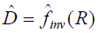
In contrast the dose-on-response method attempts to simplify the process by directly estimating a function g() such that D=g(R). Both systems estimate the parameters of their functions through ordinary least squares regression.
The direct estimate of the function g() is inappropriate, even though it may appear to be a simpler approach. These are discussed below as causality, statistical foundations, and experimental design. The actual differences of the two approaches are discussed in the last section.
Causality
There is a hierarchy of models that may be considered when developing a calibration. Ideally, an instrument’s response to a physical quantity could be derived from first principles. In this case, no estimation would be required, as the functional relationship would be completely derived. However, few systems are sufficiently well understood for this method to be available.
A second best solution is for the functional form of the relationship to be well understood, leaving only parameter values to be estimated. For example, the force of gravity between two masses is proportional to the product of their mass divided by the square root of the distance between them. The constant of proportionality is determined experimentally.
When the functional form is not known, the form and the parameters must both be estimated. In this case, causality is known (e.g. the optical density increases due to the effect of radiation), but the function describing the relationship and its parameters must be estimated. Note that it is known that radiation is not caused by the increase in optical density of radiochromic films.
In both of the two previous cases, the selection of the independent variable to be used as the domain of the function has a clear basis in the physical reality of the model. The hierarchy is ordered from a precise model of the physical relationship to increasingly less precise models of the relationship.
Finally, neither the functional form nor causality is known. An association is sought but there is no inference of causality (e.g. the popularity of cigar smoking and average stock prices). The identification of either variable as the independent or dependant variable may be somewhat arbitrary although subject to statistical restrictions discussed later.
In order to maintain a correspondence with the physics of dosimetry the model of R=f(D) is preferred to the model D=g(R).
Statistical Foundations
Statistical methods are commonly used to estimate the parameters of a function when a series of measurements have been made to form the basis of the estimate. The use of statistical software makes the estimation of function parameters extremely convenient. However, the statistical methods are based on theoretical assumptions and if these assumptions are not met, the results may not be meaningful.
Ordinary least squares regression is often used to estimate parameters of a specified functional form. This algorithm works on an equation of the form
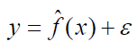
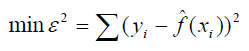
Where the hat indicates estimation and the epsilon term is a random “error”. The data used to estimate the parameters is a set of paired values of y and x (y,x). The least squares algorithm works by finding the parameters of f() that minimize the sum of squared differences between the value of y estimated by the function and the value of y actually measured at each x. i.e. minimize
When the theoretical errors, epsilon, are from independent and identically distributed normal distributions with mean 0 and variance s 2 then the parameters estimated by the least squares method correspond with the parameters estimated by a more general estimation proceedure known as maximum likelihood.
Note that the parameter estimates are based on minimizing deviations from the y (dependent) variables. When the role of dependent and independent variables are switched then the function being estimated is:
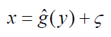
Note that because the algorithm minimized deviations in the dependent variable and assumes that the independent variable is measured without error then
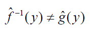
The effect of measurement error in the independent variable is discussed in Draper and Smith (N.R. Draper and H. Smith (1981) Applied Regression Analysis, second edition, John Wiley and Sons, New York, pages 122-124). Basically except under some special circumstances, the effect of uncertainty (error) in the independent variable is to bias the parameter estimates. The magnitude of the bias is proportional to the ratio of the error variance of the independent variable to the sum or squared deviations of the independent variable (roughly the range). If a choice is to be made, the independent variable should be the variable with the least uncertainty.
Fortunately for calibration, one of the special circumstances that is unbiased is the case where the independent variable is preselected as part of an experimental design. The use of Dˆ = gˆ(R) to estimate dose is thus unfortunate in several respects. First the estimate differs from the inverse f() estimate. Secondly the form of the function selects the variable with the greatest variability as the independent variable thus maximizing the bias in the estimate of the parameters of the function. And finally because the values of R are not preselected in an experimental design, the bias is not mathematically eliminated in the estimate.
Experimental Design
The design of a dosimetry calibration involves the replicate irradiation of several dosimeters at the same dose. The information provided by the replication is used for several purposes. First the replicate values obtained from several dosimeters provide a direct measure of the uncertainty associated with the measurement process independent of the estimates obtained from ordinary least squares regression. Secondly, the replicate measurements allow a goodness of fit test to be used to select an appropriate function for the calibration model.
The goodness of fit test compares the variability of the dosimeter responses about their mean at a given dose to the variability of dosimeters responses about the value predicted by the model. If the model is adequate, these should be similar. If the model is inadequate, the two measures of variability will differ significantly. The statistical value of this test is that it compares a particular model against all possible (and unspecified) alternatives. This can only be done if there are replicate measurements.
When the dosimeter response is selected as the independent variable, then there are no replicate measurements. This choice then invalidates a major part of the statistical design of the calibration experiment. Select of an appropriate model must be based on less powerful tools.
Practical Effects
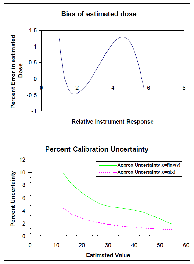
Four calibrations on two types of dosimeters were performed. The four calibrations were of the 5E4 low dose and 5E4 high dose series and the 460 low and 460 high dose series. For each case the a cubic calibration curve was fit to the data both as R=a + b*D +c*D2 + d*D3 (R=f(D) where D=f-1(R)) and as D=a + b*R + c*R2 +d*R3.(D=g(R)) The figures show the bias of the estimate of dose as a function of response and the estimated uncertainty of the estimated dose based on both methods.
As can be seen in Figures 1-4 the dose-on-response model has a bias of up to 5%. In addition, the estimated uncertainty of the calibration, a component of the total uncertainty, may vary by a factor of 2 from the statistically correct uncertainty estimates. Whether the uncertainty estimate is over-estimated or under-estimated depends on the slope (first derivative) of the response curve. For these curves, the uncertainty is generally underestimated.
Figure 1 - 5E5 Low Dose Range
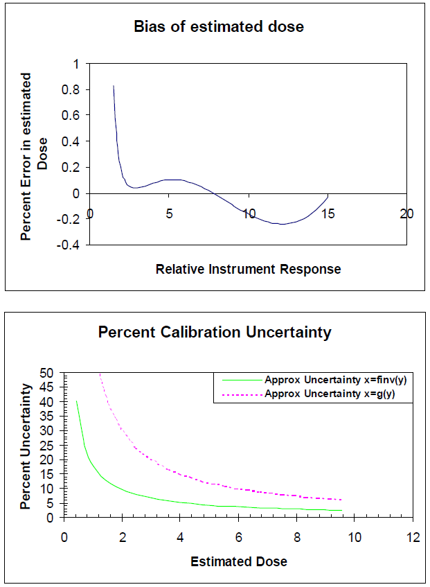
Figure 2: 5E4 High Dose Range
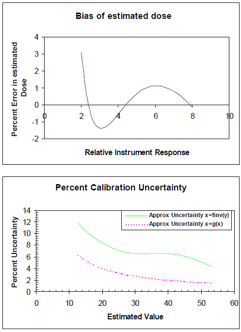
Figure 3 - 460 Low Dose Range
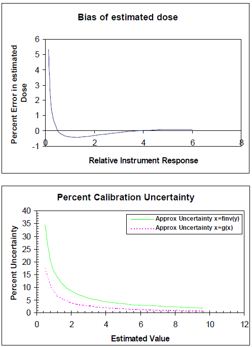
Figure 4 - 460 High Dose Range
Disclaimer -The information contained in this document is provided “as is” and is not a substitute for the user’s professional judgement. It is provided as a convenience to those using products provided by GEX Corporation who have sufficient technical skills to evaluate and properly apply the information in this document. It is the responsibility of the user of this document to ensure that the information in this document, and the use of such information, is accurate, complete, applicable to the product, suitable for the user’s purposes, and in compliance with all laws and regulations. GEX Corporation believes the information provided in this document is accurate and reliable as of the time of writing, but it undertakes no obligation to update or correct this document. GEX Corporation may, but is not required to, make changes to this document at any time without notice. By using the information in this document, the user represents and warrants that he or she has the skills necessary to properly understand and apply this information and that he or she will comply with all applicable laws and regulations including, without limitation, those relating to medical devices, pharmaceutical products, or other applicable industries. The user assumes all risks associated with using this information and any results or output resulting from the application of this information to GEX Corporation’s products. The user agrees not to hold GEX Corporation liable for any errors or omissions contained within.